



When a deformable body is loaded externally, its internal particles exert forces on one another to hold the body together. Understanding these internal forces is the core objective of Mechanics of Materials, as they determine whether a structure will safely support its loads or fail.
1. External Loading vs. Internal Response
In structural mechanics, a body is subjected to various types of external forces, which can be categorized as:
- Applied Forces: Active external loads acting on the body, such as gravity loads, traffic loads on a bridge, or wind forces.
- Support Reactions: Reactive external forces exerted on the body by its supports (such as pins, rollers, or fixed foundations) to restrict movement and maintain global static equilibrium:
\(\Sigma \vec{F} = 0, \quad \Sigma \vec{M} = 0\)
While Statics stops at calculating these external reactions, Mechanics of Materials looks inside the body. When external loads tend to pull apart, compress, or shear a structural member, the material's internal bonding forces resist these tendencies. This internal resistance is what we call internal forces. If the external loads exceed the maximum internal resistance of the material, microscopic cracks initiate, leading to macroscopic deformation and eventual structural failure.
2. The Method of Sections (Imaginary Cut Principle)
Internal forces are, by definition, hidden inside the material. To make them accessible to mathematical calculation, engineers utilize one of the most powerful tools in mechanics: The Method of Sections.
This principle is based on a simple but profound hypothesis:
If a structural body is in global static equilibrium, then any isolated segment of that body must also be in static equilibrium. This means the equations of equilibrium remain perfectly valid for any portion of the structure
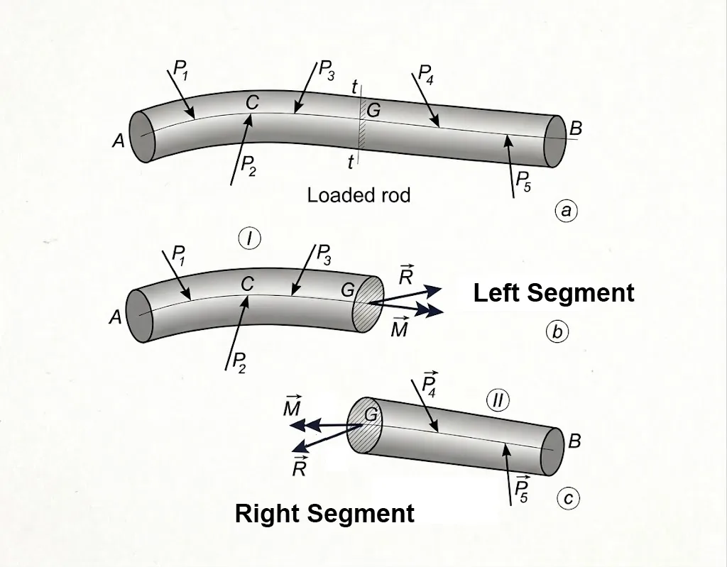
The Method of Sections consists of four sequential steps:
- Global Equilibrium: Solve for any unknown external support reactions by treating the entire structure as a single rigid body.
- The Imaginary Cut: Pass an imaginary plane (cross-section) through the specific point of interest, dividing the member into two distinct parts (e.g., Left Segment and Right Segment).
- Isolate and Expose: Choose one of the segments (usually the simpler one with fewer loads) and draw its Free-Body Diagram (FBD). The internal forces that previously held the two segments together are now exposed on the cut surface as external forces acting on that segment.
- Apply Local Equilibrium: Apply the equations of static equilibrium to the isolated segment to solve for the unknown internal forces.
3. 3D Internal Force Components
When we cut a 3D structural bar, the distributed internal stress field acting across the cut surface can be mathematically replaced by an equivalent force-couple system acting at the centroid (G) of the cross-section. This system is fully characterized by 3 independent internal force components and 3 independent internal moment components .
To align with modern engineering computation and clear visualization, we establish the following standardized right-handed coordinate system:
- \(x\)-Axis (Beam Axis): Directed longitudinally along the undeflected neutral axis of the bar (from left to right).
- \(y\)-Axis (Vertical Axis): Lying within the cross-sectional plane, pointing vertically upward.
- \(z\)-Axis (Horizontal Axis): Lying within the cross-sectional plane, pointing horizontally outward to form a standard right-handed system.
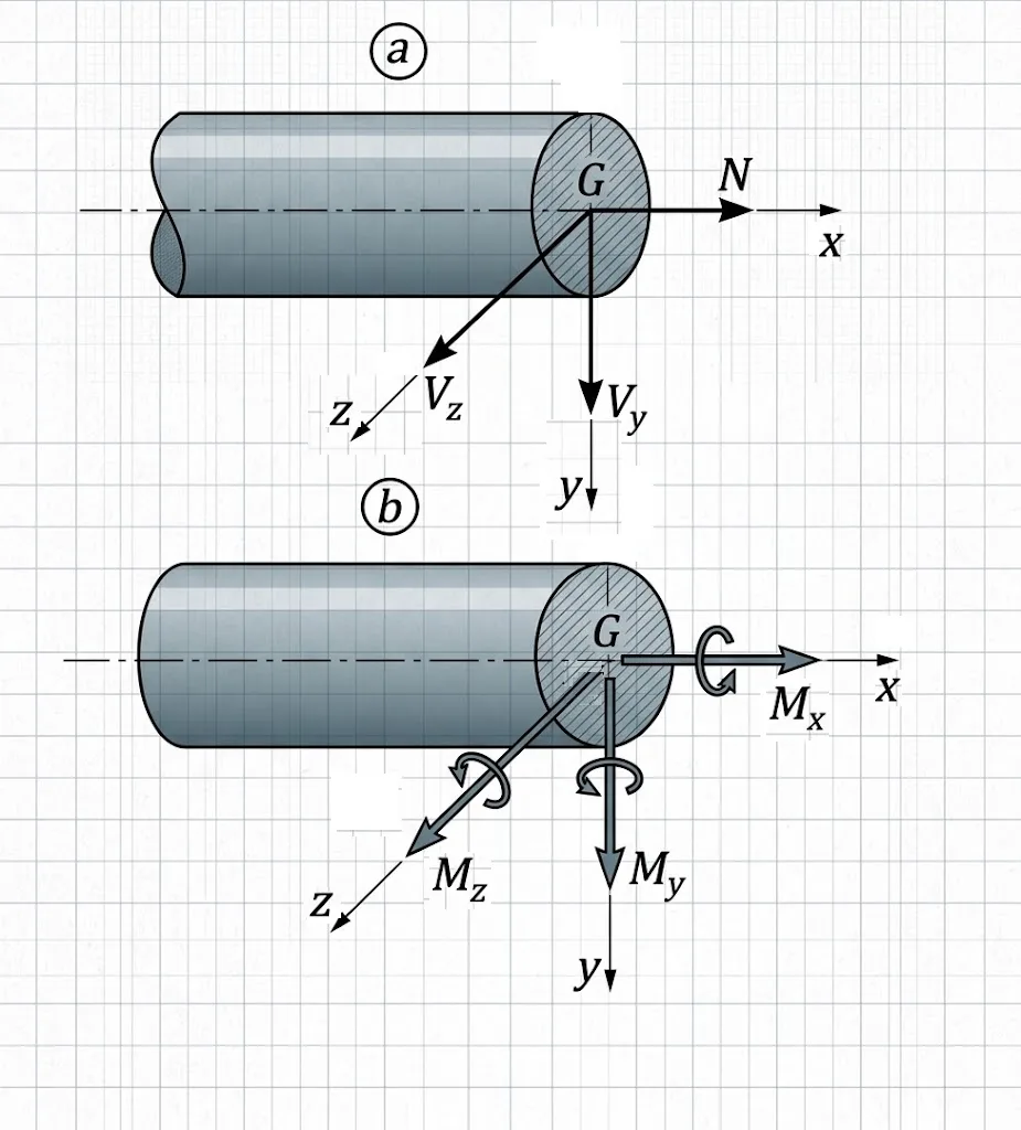
Under this coordinate system, the six internal load components acting at centroid \(G\) are defined as:
- Normal Force, \(N\): Acts perpendicular (normal) to the cross-section along the longitudinal \(x\)-axis. It represents resistance to stretching (tension, \(N > 0\)) or crushing (compression, \(N < 0\)).
- Shear Forces, \(V_y\) and \(V_z\): Act tangent to the cross-section within the \(yz\)-plane.
- \(V_y\): The vertical shear force component, resisting relative vertical sliding.
- \(V_z\): The horizontal shear force component, resisting relative horizontal sliding.
- Torsional Moment, \(T\) (or \(M_{x}\)): Represents the couple moment acting about the longitudinal \(x\)-axis, resisting twisting of the bar.
- Bending Moments, \(M_y\) and \(M_z\): Couple moments acting about the cross-sectional axes:
- \(M_z\): Bending moment acting about the horizontal \(z\)-axis, causing bending deformation within the vertical \(xy\) plane. This is the primary bending moment studied in classical beam theory.
- \(M_y\): Bending moment acting about the vertical \(y\)-axis, causing bending deformation within the horizontal \(xz\) plane.
4. Sign Conventions for 3D Internal Forces (Right-CS vs. Left-CS)
To establish a consistent mathematical framework for internal forces across a 3D structural member, we define the sign conventions based on the orientation of the cross-sectional face created by an imaginary cut.
Definition of Right-CS and Left-CS
When an imaginary cut is passed through a bar, two opposite cross-sectional faces are exposed, categorized by the direction of their outward normal vector \(\vec{n}\):
- Right Cross-Section (Right-CS / Positive Face): The cross-section whose outward unit normal vector points in the positive direction of the longitudinal coordinate axis (\(+x\)-axis). This face is located on the right side of the left segment.
- Left Cross-Section (Left-CS / Negative Face): The cross-section whose outward unit normal vector points in the negative direction of the longitudinal coordinate axis (\(-x\)-axis). This face is located on the left side of the right segment.
Positive Directions in 3D
The sign convention for internal forces and moments in three dimensions is directly tied to whether the forces act on a Right-CS or a Left-CS:
• On a Right Cross-Section (Right-CS): An internal force or moment component is defined as positive (+) if its direction vector points in the SAME direction as the corresponding positive coordinate axes (\(+x, +y, +z\)).
• On a Left Cross-Section (Left-CS): An internal force or moment component is defined as positive (+) if its direction vector points in the OPPOSITE direction to the corresponding positive coordinate axes (\(-x, -y, -z\)).
| Internal Component | Positive Direction on Right-CS (+ Face) | Positive Direction on Left-CS (- Face) |
|---|---|---|
| Normal Force (\(N\)) | Along \(+x\) (Outward / Right) | Along \(-x\) (Outward / Left) |
| Shear Force (\(V_y\)) | Along \(+y\) (Upward) | Along \(-y\) (Downward) |
| Shear Force (\(V_z\)) | Along \(+z\) (Outward) | Along \(-z\) (Inward) |
| Torsion (\(T = M_x\)) | About \(+x\) axis (Right-hand rule thumb along \(+x\)) | About \(-x\) axis (Right-hand rule thumb along \(-x\)) |
| Bending Moment (\(M_y\)) | About \(+y\) axis (Right-hand rule thumb along \(+y\)) | About \(-y\) axis (Right-hand rule thumb along \(-y\)) |
| Bending Moment (\(M_z\)) | About \(+z\) axis (Counterclockwise in \(xy\)-plane) | About \(-z\) axis (Clockwise in \(xy\)-plane) |
Notice that by Newton's Third Law (Action-Reaction), the positive directions on the Right-CS and Left-CS are equal in magnitude and opposite in spatial direction, ensuring that when two segments are rejoined, the internal forces cancel out externally.
5. Coplanar Force System (2D System) and Positive Directions
In many practical engineering problems, a structural member is subjected to a coplanar force system, where all applied forces, loads, and reaction forces lie strictly within a single plane—specifically the vertical \(xy\)-plane of symmetry.
Active Internal Forces in Coplanar Loading: When external loadings are confined to the \(xy\)-plane, three of the six 3D internal force components naturally vanish due to symmetry:
- \(V_z = 0\) (no out-of-plane horizontal shear force)
- \(T = M_x = 0\) (no torsional moment twisting about the longitudinal \(x\)-axis)
- \(M_y = 0\) (no out-of-plane bending moment about the vertical \(y\)-axis)
Therefore, a coplanar force system yields exactly three active internal force components: Normal Force (\(N\)), Shear Force (\(V_y\)), and Bending Moment (\(M_z\)).
Direction of View and Dotted Line Convention:
The positive directions of internal forces and internal moments are determined with the help of the right and left cross-sections, which are established according to the direction of view.
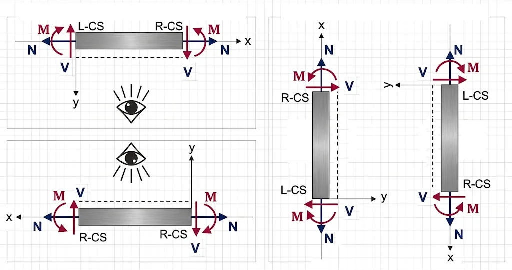
- Direction of View: The coordinate axes of a bar (member) run from left to right relative to the chosen direction of view. In structural engineering drawings, a dotted line is placed along the reference side (bottom fiber) of the bar to explicitly indicate the direction of view.
- Right Cross-Section (Right-CS): On the cross-section whose outward normal points in the positive longitudinal axis direction, internal forces and moments are defined as positive (+) when placed in the same direction as the coordinate axes.
- Left Cross-Section (Left-CS): On the cross-section whose outward normal points in the negative longitudinal axis direction, internal forces and moments are defined as positive (+) when placed in the opposite direction of the coordinate axes.
Positive Directions in 2D Beam Analysis: Applying the Right-CS and Left-CS rules relative to the direction of view establishes the standardized 2D Beam Sign Convention:
| Internal Component | Positive Definition on Right-CS (+ Face) | Physical Effect / Deformed Shape |
|---|---|---|
| Normal Force (\(N\)) | Points in the positive \(x\) direction (outward / right) | Tension: Tends to stretch the bar. |
| Shear Force (\(V_y\)) | Points in the positive \(y\) direction (downward on Right-CS, upward on Left-CS) | Clockwise Rotation: Tends to rotate the isolated beam segment clockwise. |
| Bending Moment (\(M_z\)) | Acts about \(+z\) axis on Right-CS (about \(-z\) axis on Left-CS) | "Smiling Beam": Concave upward bending toward the direction of view side (dotted line). Compresses top fibers, stretches bottom fibers. |
• Direction of View (Dotted Line): Establishes the orientation of left-to-right longitudinal axis. The dotted line indicates the tension side for positive bending.
• Right Cross-Section (+ Face): Internal forces are positive (+) when pointing in the direction of the coordinate axes.
• Left Cross-Section (- Face): Internal forces are positive (+) when pointing in the opposite direction of the coordinate axes.
• Positive Tensile Force (\(N > 0\)): Always points outward away from the cut face.
• Positive Shear Force (\(V > 0\)): Points downward (\(+y\)) on a Right-CS and upward (\(-y\)) on a Left-CS, producing a clockwise rotational tendency.
• Positive Bending Moment (\(M > 0\)): Causes concave upward bending toward the dotted line (direction of view).