


In structural analysis, we represent complex three-dimensional structural members as simplified one-dimensional models to make mathematical calculations highly efficient and practical.
1. Structural Systems and Their Classification
Structures in civil, mechanical, and aerospace engineering are designed to bear loads and transmit them safely to the ground or other supports. To analyze these load-carrying systems, we classify them into three main categories based on their physical dimensions:
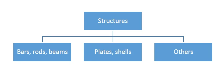
- Bars (One-Dimensional / Slender Structures): Structural members where one dimension (the length) is significantly larger than the other two cross-sectional dimensions (width and height). Typical engineering examples include:
- Beams: Horizontal elements designed to carry loads acting perpendicular to their longitudinal axis.
- Columns: Vertical elements that carry heavy compressive axial forces.
- Arches: Curved structures that translate bending loads primarily into compression.
- Plates and Shells (Two-Dimensional / Thin Structures): Structural elements where one dimension (the thickness, \(t\)) is significantly smaller than the other two dimensions (length and width). They are divided into:
- Plates: Flat, straight structural systems loaded perpendicularly to their plane (e.g., concrete floor slabs, shear walls).
- Shells: Thin, curved-surface structures that carry in-plane and membrane forces efficiently (e.g., dome roofs, vaults, pressure vessels).
- Other Structures (Three-Dimensional / Massive Structures): Solid, bulky bodies where there is no dominant dimension; all three physical dimensions are of a similar scale. Typical examples include concrete gravity dams, heavy machinery foundations, and thick retaining walls.
2. Bar Structures
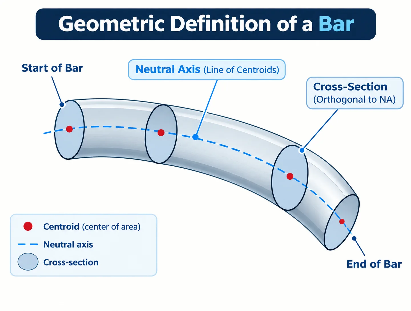
In the study of Strength of Materials, we almost exclusively focus on bar structures. A bar is defined as a straight or curved slender structural member designed to carry axial, shear, or bending loads. Analyzing 3D elasticity equations for every structural member would be computationally impossible and practically redundant. By utilizing the geometric simplifications of bar structures, we reduce complex three-dimensional problems into elegant and solvable one-dimensional mathematical formulations.
3. Neutral Axis and Cross-Section
A bar is completely defined and mathematically characterized by two fundamental geometric components:
- Neutral Axis (Centerline / Line of Centroids): The longitudinal reference line of the bar. It is the locus of the centroids (\(G\)) of all the cross-sections along the length of the member. Depending on the design, the neutral axis can be:
- Straight Neutral Axis: Found in prismatic beams, columns, and straight rods.
- Curved Neutral Axis: Found in arches and curved beam elements.
- Cross-Section: The plane shape obtained by cutting the bar perpendicular to its longitudinal neutral axis.
At any point along the bar, the cross-section is strictly mutual (perpendicular and orthogonal) to the tangent of the neutral axis. This perpendicularity is a core kinematic assumption required to establish consistent internal force and stress distributions.
4. Uniform and Nonuniform Bars
Depending on how the cross-sectional shape and area vary along the length of the neutral axis, bars are classified into two main structural types:
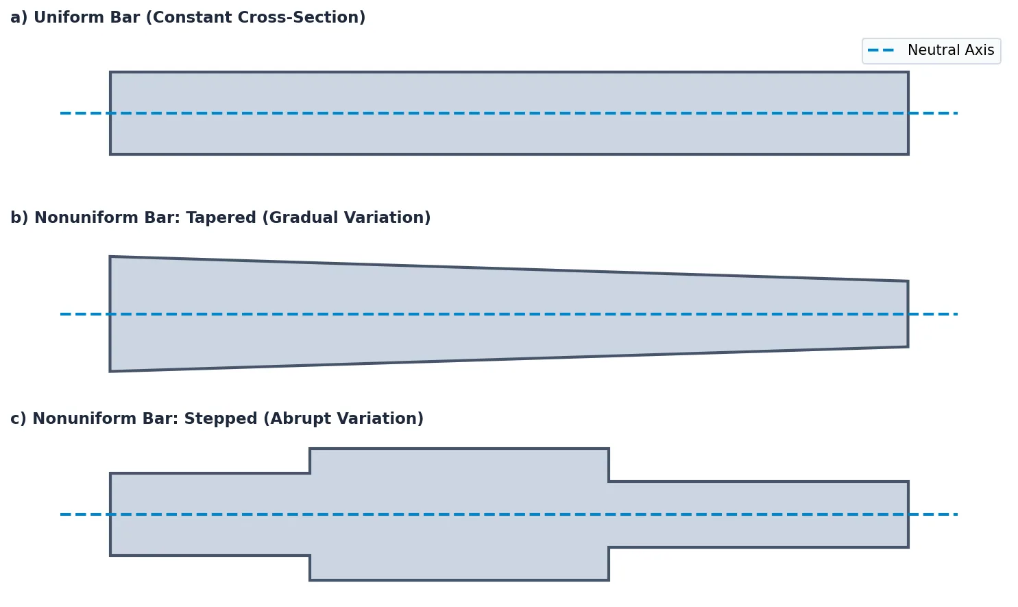
- Uniform Bars (Prismatic Bars): The shape, dimensions, and area (\(A\)) of the cross-section remain completely constant throughout the entire length of the bar. Standard rolled steel I-beams or rectangular timber columns are common examples.
- Nonuniform Bars (Non-prismatic Bars): The cross-sectional properties vary along the longitudinal axis of the bar. These are further sub-classified into:
- Tapered Bars: The cross-section varies gradually and continuously along the length of the neutral axis as a mathematical function of position, \(A = A(z)\). These are often engineered to optimize material efficiency (mass reduction) where internal bending moments are lower.
- Stepped Bars: The cross-sectional dimensions change abruptly at discrete stages or intervals along the bar. These are common in machine shafts, multi-level building columns, or where different member segments are spliced together.
In structural mechanics, a change in cross-section directly alters the bar's axial rigidity (\(EA\)) and flexural rigidity (\(EI\)). For tapered bars, deformations must be calculated using integration rather than simple multiplication. For stepped bars, the abrupt change in geometry creates severe local stress concentrations at the step boundaries. This requires special local stress factors to prevent crack initiation and fatigue failure.
5. Idealization of a Bar
To establish a consistent, solvable mathematical theory, we perform an idealization process. This process simplifies a real, physical three-dimensional solid member into a one-dimensional mathematical bar using the following fundamental assumptions:
- 1D Reference Representation: The physical bar is represented by its 1D neutral axis (centerline). All external loads (concentrated forces, moments, and distributed line loads) are mathematically projected and assumed to act directly on this reference centerline.
- Cross-Section as a Compacted Property: The complex 3D volume of the member is compacted into mathematical properties assigned to each point on the 1D neutral axis. These geometric properties include:
- Area (\(A\)): Governs axial stiffness and uniform normal stress.
- Moment of Inertia (\(I\)): Governs bending stiffness and resistance to rotation.
- Polar Moment of Inertia (\(J\)): Governs torsional rigidity and shear resistance.
- Bernoulli's Hypothesis (Plane Sections Remain Plane): Any cross-section that is plane and perpendicular to the neutral axis before deformation remains strictly plane and perpendicular to the neutral axis after deformation. Transverse shearing deformations within the cross-section are neglected (valid for slender beams).
- Small Displacement Assumption: The deflections, rotations, and strains are assumed to be so small that the equations of static equilibrium can be written using the original, undeformed geometry of the structure.